Hardware
What RS-Key runs on, and the build knobs you need for a board other than the reference one. The full knob reference is in build.md. This page is the short version.
Supported boards
 |
 |
 |
 |
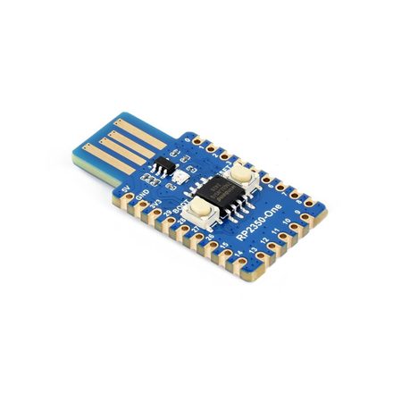
| RP2350-One reference · USB-A WS2812 on GPIO16 |
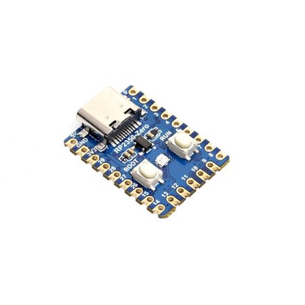
RP2350-Zero mini stick · USB-C |
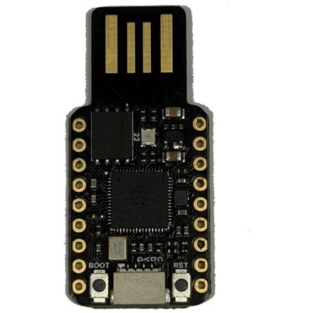
TenStar RP2350-USB USB-A stick WS2812 on GP22 |
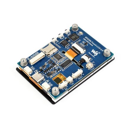
RP2350-Touch-LCD-2.8 trusted display · 2.8″ LCD |
Board photos: Waveshare (RP2350-One / Zero / Touch-LCD-2.8).
Any RP2350 board with a USB connector should work. Development and on-device
testing happen on the Waveshare RP2350-One, where the WS2812 status LED on
GPIO16 works out of the box. Boards without an addressable LED run fine. The
indicator is optional and the firmware just runs dark. A board whose LED sits
behind a power gate — the Seeed XIAO RP2350 powers its WS2812 through GP23 —
lights up once that enable pin is set with LED_POWER_PIN (below).
The RP2350’s dual Cortex-M33, 520 KB SRAM, hardware TRNG, OTP fuses, and glitch detectors do the work. There is no secure element and no debugger requirement: the firmware flashes over USB BOOTSEL, so a bare board and a USB cable are enough.
Defaults and the knobs to change them
The default build targets a 4 MB flash chip with the LED on GPIO16, uses BOOTSEL for user presence, and assumes a standard 12 MHz crystal. For a different board, three compile-time knobs usually cover it:
| Knob | Default | When to change it |
|---|---|---|
FLASH_SIZE | 4M | A board with a different QSPI flash chip (e.g. 8M). build.rs regenerates memory.x from it. Must be ≤ 16 MB and leave ≥ 1 MB for code after the KV store; a 2 MB board also needs a smaller KVMAIN (below). |
KVMAIN | 1408K | A 2 MB board (Seeed XIAO RP2350, Waveshare RP2350-Zero-CM): the default 1408K KV main partition leaves too little for the ~900K image. Shrink it — FLASH_SIZE=2M KVMAIN=896K — to fit. A fully provisioned key uses only a few hundred KB. See build.md. |
LED_PIN | 16 | A board that uses GPIO16 for something else, or wires its addressable LED elsewhere (RP2350A: GPIO 0..=29). |
LED_POWER_PIN | none | A board whose LED sits behind a power gate that must be driven high to light it (e.g. the Seeed XIAO RP2350’s WS2812 on GP23). Set the enable GPIO; it must differ from LED_PIN and any GPIO PRESENCE_PIN. |
USR_LED_PIN | none | A board with a nuisance onboard user LED that lights by default (the Seeed XIAO RP2350’s active-low USR LED on GP25). Set the GPIO to park it off at boot; flip USR_LED_ACTIVE_HIGH=1 for an active-high LED. Must differ from LED_PIN, LED_POWER_PIN, and any GPIO PRESENCE_PIN. |
PRESENCE_PIN | bootsel | A board with a dedicated user-presence button on a GPIO. Set a pin number (0..=29); active-low with a pull-up by default (e.g. 0 for GPIO0-to-GND). |
PRESENCE_ACTIVE_HIGH | 0 | A presence button/sensor that reads high when pressed (a capacitive touch sensor, or a button to VCC). 1 flips the GPIO to pull-down + active-high. Only with a GPIO PRESENCE_PIN. |
LED_KIND | ws2812 | ws2812 (addressable RGB, default), gpio (plain on/off), pimoroni (3-pin PWM RGB), or none (no indicator). See build.md. |
LED_ORDER | rgb | A ws2812 board whose red and green come out swapped (blue fine): set grb (the WS2812B standard). The Waveshare RP2350-One is rgb; most other parts are grb. |
MAX_LEDS | 8 | A board with more than 8 daisy-chained addressable LEDs. The buffer ceiling; the actual connected count is set at runtime (guides/led.md). |
# example: an 8 MB board with a plain LED on GPIO25
env FLASH_SIZE=8M LED_KIND=gpio LED_PIN=25 cargo build --release -p firmware

# example: a 16 MB TenStar RP2350-USB — WS2812 on GP22, standard GRB order
env FLASH_SIZE=16M LED_PIN=22 LED_ORDER=grb cargo build --release -p firmware

# example: a Seeed XIAO RP2350 — WS2812 on GP22, GRB, power-gated by GP23 (driven high),
# its active-low USR LED on GP25 parked off, and its 2 MB flash (smaller KVMAIN)
env FLASH_SIZE=2M KVMAIN=896K LED_PIN=22 LED_ORDER=grb LED_POWER_PIN=23 USR_LED_PIN=25 cargo build --release -p firmware

# example: WS2812 on GP22 and a button-to-GND on GP0 (active-low)
env LED_PIN=22 PRESENCE_PIN=0 cargo build --release -p firmware

# example: an active-high capacitive touch sensor on GP0
env PRESENCE_PIN=0 PRESENCE_ACTIVE_HIGH=1 cargo build --release -p firmware
The four LED knobs (LED_PIN / LED_KIND / LED_ORDER / MAX_LEDS) set only the
boot defaults. A non-none build compiles all three backends, so the pin,
driver, wire order, and buffer ceiling are also changeable at runtime (no
reflash) with rsk hw or PicoForge, which write them to the device’s phy
record
(guides/led.md). The build knobs still matter for picking a
lean none build and for the out-of-the-box default.
Most RP2350A boards work with at most a one-line change. Everything else (USB descriptors, applets, flash layout) is board-independent.
Enclosures
A bare board works fine, but a printed case makes it pocketable. Four community designs fit the boards above:
- Waveshare RP2040-One / RP2350-One case by Patrick van der Leer. Sized for the reference board.
- RP2350 USB case by Vladimir Varzaru (a remix of Patrick’s design). A slimmer USB-stick form.
- Pico 2 Zero FIDO2 case (RP2350) on MakerWorld. Fits the RP2350-Zero.
- Waveshare RP2350 2.8-inch case by @cofob. Designed for RS-Key and recommended for the RP2350-Touch-LCD-2.8. PETG is the recommended print material.
- Waveshare RP2350 2.8-inch case by Mono. Designed for RS-Key, reliable USB and button performance as well as sturdyness. PETG material recommended.
The two Printables designs as well as the Thingiverse design are licensed CC BY-SA 4.0: print, sell, and remix them freely, as long as you credit the authors and keep any derivative under the same license. Check each MakerWorld page for the design license before you reuse the design. All are third-party designs, linked for convenience, not part of this project.
What the hardware does not give you
The OTP fuses and secure boot (production.md) are real hardening, but the RP2350 is a general-purpose microcontroller, not a certified secure element. Physical attacks are out of scope: decapping, microprobing, fault injection beyond the on-chip glitch detectors, power/EM side channels. See the threat model and limitations.